-

Happy Holidays 2025
May the coming year bring you peace, joy, and continued success. We look forward to achieving great things together in the year ahead!
-

MontaVista has joined Linux Foundation Europe
Together, we strengthen open source collaboration across Europe and beyond, building a sustainable ecosystem for all.
-

MVSecure allows hassle-free compliance with EU and US cybersecurity regulations!
Ensure your ICT products, services, and processes meet EU and US cybersecurity standards with ease. We provide ready-to-use solution templates for your certification journey under the EU Cyber Resilience Act (CRA) and the US Executive Order on Cybersecurity.
-

Facing challenges with Kubernetes on embedded Linux systems?
MontaVista’s MVKube simplifies integration and management of Kubernetes in embedded Linux environments with professional support for current deployments and the latest releases.
-
Looking to upgrade your embedded applications? Get MontaVista Linux CGX 5.0!
Built on the Yocto Project 5.0 LTS and the Linux kernel 6.6 LTS, MontaVista CGX 5.0 offers AI-ready and Secure-by-Design features in a single platform.
-
We support CentOS 7 beyond June 2024. Contact us today!
MontaVista's MVShield continues stability and security for your custom CentOS 7, including critical CVE updates, bug fixes and technical support until at least another decade.
-

New to Rocky Linux? Get in touch today!
MVShield provides technical support on Rocky Linux baselines for at least 10 years.
Latest News
APPLICATIONS
SBOM generation and management are at the heart of MontaVista’s security-first strategy. Backed by over two decades of Linux and cybersecurity expertise, MontaVista strengthens the software supply chain through its integrated ecosystem—CGX, MVShield, and MVSecure—built on Secure-by-Design and Zero Trust architectures, and continuous vulnerability management.

Cybersecurity threats are growing more sophisticated, and newly disclosed vulnerabilities (CVEs) continue to pose serious risks. For organizations using Linux in embedded or mission-critical systems, staying ahead means not just tracking CVEs, but addressing them without compromising stability or performance.

SOLUTIONS


MARKETS


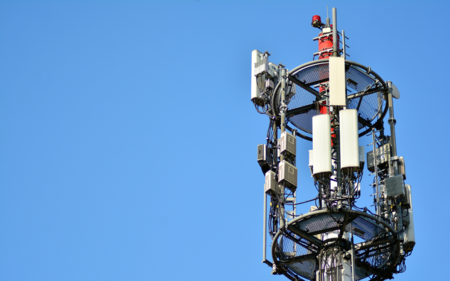
MontaVista's root are in the Telecom and Networking space, the company was founded on the idea of Carrier Grade Linux and bringing real-time responsiveness into the Linux realm. We have a thorough understanding of the needs of networked devices and providing solutions in this space.