CAN Bus - Episode 1: Introduction to CAN Bus
Before we dive into the details of CAN Bus, it helps to understand some of the design principles and some of the historical background from when, and why, CAN was invented in the first place, before we show how it fits into the Automotive world of today, and how we can interact with it.
History of CAN Bus
Let’s take a look at how vehicle functions were controlled before the introduction of CAN Bus.
In Europe CAN was pioneered by BOSCH (an automotive Tier 1 supplier) and introduced by Mercedes-Benz into high-end luxury cars (with many electronic features) in 1991, with widespread adoption (in Europe and Japan) in the 2000’s. In the USA, CAN Bus gained popularity in the late 1990s and late 2000’s. For more information about CAN Bus, see the article here.
Before CAN Bus
Cars have evolved significantly from the early days of the beginning of automobiles.
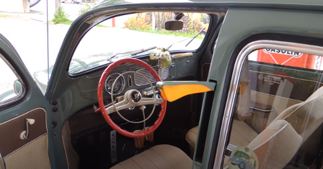
This is the picture of an actual, mechanical, flip-up turn indicator and the dashboard of a 1950’s VW Bug.
In the time before widespread CAN Bus usage, every actuator in a car had to be wired to all necessary sensors.
The gauge which displays the engine temperature to the driver, has a dedicated wire to the sensor in the engine block. This not only requires a LOT of wires throughout the car (some cars can have up to 5 miles of wires, weighing over 100lbs) but it also makes it hard to have centralised devices such as a engine controller which require connections to many other sensors. One example is the wheel-speed of the vehicle, which is required by many different controllers, the ABS, Engine Management, Navigation, and the Dashboard to just name a few.
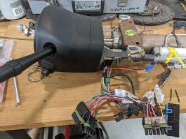
The picture above shows a pre-CAN Bus steering column with all the wiring needed for headlight, turn-signal, high/low beam, wiper control (with speed settings) and cruise-control in a 1997 GM Corvette C5.
How CAN Bus simplified the Automotive Wiring
The first use for CAN Bus was to simplify the growing complexity of Engine Management (where it replaced things like vacuum actuated ignition timing control systems) and other critical systems such as Anti Lock Brakes (ABS). Therefore, CAN was from the very beginning designed to be high reliability and safety critical interconnection protocol.
With CAN Bus, the point-to-point analog connections between sensors and actuators are replaced by a high-speed (Initially 1MBit) serial communication bus.
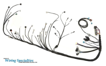
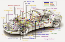
See this image for a modern Engine Wiring Harness, and next to it a conceptual view of a modern vehicle bus topology. For a deeper dive into CAN see the paper here.
Advantages of CAN Bus
Besides being designed from the ground up for safety critical, high reliability operation, the CAN Bus connected devices also had to be able to be manufactured cheaply. This meant it had to be a very simple protocol (unlike Ethernet), using complicated glassfiber or coax wiring (unlike MOST) implementable on very low-power, 16 and 32 bit microcontrollers with cheap, high volume chipsets. Today, the cost of adding CAN bus support to an automotive controller has to be cheaper than running another dedicated wire.
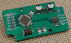
The below image shows a very cost efficient CAN enabled board which can be used to perform various I/O functions.
Other Automotive Bus Standards
Throughout the last 20 years, several other domain specific networking standards have been introduced in automotive bus systems. For a good overview see here.
For simplicity this Blog series will focus primarily on CAN Bus.
To find out more about MontaVista's Automotive solutions, you can find more information here. Or contact us if you would like to discuss your new design together!